Practice Project for Systems Engineering - Part 2
Part 1 was all whiteboards and sticky notes: we argued over requirements, carved a latency budget, and froze a mission that could be proven on a kitchen table. That was the left-hand descent of the V-model.
Part 2 begins the climb up the right-hand side. Here the abstractions acquire voltages, GPIO pins and FreeRTOS tasks. We will:
-
Pin every SMART requirement to a functional block. You'll see a tight sense → estimate → decide → act pipeline that closes in 10 ms—fast enough to intervene five times before the car has rolled a single wheel-diameter.
-
Choose silicon and copper that can't mis-brake. A $20 QuicRun ESC supplies dynamic-braking torque, an ELRS receiver delivers low-loss throttle frames, and a $1 74HC157 mux makes sure the radio always has veto power if firmware dies.
-
Split software into four clean layers. The Application layer ships features; the Domain layer does the math; the Service layer adapts ports; HAL drivers and RTOS tasks sit at rock bottom. Every layer is unit-testable on a PC.
-
Give the driver two eyes, not one. A WildFire Nano AIO camera/VTx provides a 13-17 ms analogue feed for racing, while the ESP32 still pushes MJPEG over Wi-Fi for bench work. The two links share nothing but a battery, so congestion on one can't sink the other.
By the end of this part you'll have the full bill-of-materials, a layered codebase skeleton, and concrete verification hooks—all ready for the soldering iron. If Part 1 was the blueprint, Part 2 is the build manual. Let's zoom in.
DISCLAIMER: I haven't done extensive testing for the hardware pieces included in the project. Since this is an exercise, I "trusted" GPT o3 with the estimates for the latencies and such. If I were planning to carry on with this project, a whole verification and validation process would need to be done for those parts.
1 Functional Architecture - What the System Does
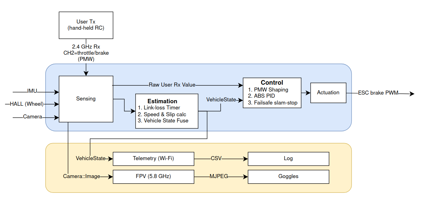
In classical control parlance this is a sense → estimate → decide → act pipeline. The feedback loop closes every 10 ms, giving the controller five fresh opportunities to intervene during the 25 ms it takes the car to travel 20 cm at 30 km h⁻¹.
| Block | Prime SMART reqs |
|---|---|
| Sensing | FR-4 |
| Estimation | FR-1a, FR-2 |
| Control | FR-1b, FR-2 |
| Telemetry | FR-3, FR-4 |
Anything that cannot be traced forward to a requirement,or backward to a verification step,gets chopped as scope-creep.
2 Physical Architecture - What the System Is
As with other parts of the series, selecting certain parts, such as the MCU, ESC, Servos, etc., must be carefully considered. Here, I'm "trusting" the LLM (GPT o3) to select for me, but if I were to build the system, I would refine this part in detail.
| Sub-assembly | Main parts & interfaces | Power domain |
|---|---|---|
| Chassis & drive | WLtoys 144001 buggy, HobbyWing QuicRun 16BL30 ESC, stock steering servo | Li-Po raw |
| Radio link | ELRS receiver (S.Bus 100 Hz) | 5 V BEC |
| Compute module | ESP32-S3-CAM dev-kit, on-board Wi-Fi/BLE, 8 MB PSRAM | 5 V buck |
| Safety-mux | 74HC157 quad 2-to-1 PWM mux + RC watchdog gate (GPIO feed from ESP32) | 5 V buck |
| Sensing frontend | • Hall sensor (rear-left wheel) • BMI270 IMU (SPI) | 3 V3 LDO |
| Vision frontend | OV2640 camera on ESP32 | 3 V3 |
| FPV link | Foxeer WildFire Nano VTx 25/200 mW + 600 TVL AIO cam (NTSC) | 5 V buck |
| Power chain | MP1584 buck (11 V→5 V) → AMS1117 (5 V→3 V3) | - |
| User I/O | RGB status LED, push-button mode select | 3 V3 |
| Test/Debug | SWO/UART header, 8-ch logic-analyser pin-out | 3 V3 |
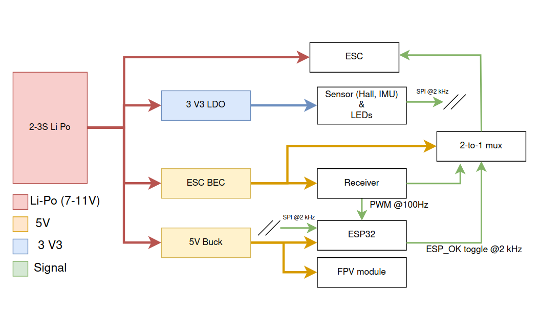
Design intent
- Fail-silent hardware path. Radio PWM always has a physical lane to the ESC. The ESP32 takes over only while a watchdog-toggled GPIO keeps the mux selected; loss of toggling (<30 ms) reverts to radio.
- All life-critical loads share the main Li-Po rail—if SmartDrive-XR dies, the driver regains stock control immediately.
- WildFire Nano gives a sub-10 ms FPV feed for racing; Wi-Fi MJPEG stays for bench work.
3 Software Architecture - Where Behaviour Lives in Time
3.1 Layered View
┌────────────────────────────────────────────────────────────┐
│   Application layer ("features")                           │
│    • ABSController • FailsafeManager • LatencyProfiler     │
│    • FpvOsdManager                                         │
│────────────────────────────────────────────────────────────│
│   Domain layer ("business logic")                          │
│    • VehicleState • PwmShapeStrategy • ControlLaw (PID)    │
│    • StateEstimation                                       │
│────────────────────────────────────────────────────────────│
│   Service layer ("ports & adapters")                       │
│    • StateProvider • SpeedCommander • CsvLogger            |
|    • MjpegStreamer • FpvMonitor (RSSI) • **PwmMuxDriver**  │
│────────────────────────────────────────────────────────────│
│   HAL + RTOS (drivers & tasks)                             │
│    • imu\_bmi270.c • hall\_driver.c • esc\_pwm\_driver.c   │
│    • fpv\_rssi\_adc.c • pwm\_mux\_driver.c                 │
│    • cam\_dma.c • wifi\_sta.c • rtos\_task\_mgr.c          │
└────────────────────────────────────────────────────────────┘
Why this split?
- Application layer answers "What feature do I ship?"
- Domain layer answers "What maths / logic makes it correct?"
- Service layer answers "How do I talk to IO, network, storage?", using Port-and-Adapter (Hexagonal) pattern.
- HAL + RTOS hides silicon specifics, keeping everything above unit-testable on the host.
3.2 Core Design Patterns
| Pattern | Anchor module | Why it matters |
|---|---|---|
| Hexagonal | StateProvider, SpeedCommander, FpvMonitor | Swap real drivers for mocks in CI |
| Strategy | PwmShapeStrategy | Tune brake feel live over CLI |
| Command | BrakeCommand → driver queue | Decouples 10 ms maths from µs PWM |
| State Machine | FailsafeManager | Formal RUN → DECEL → STOP → IDLE |
| Observer | event_bus.h | Zero-copy pub-sub between tasks |
| DI (manual) | app_init() | Tests inject mocks; prod wires HW |
3.3 RTOS Task Model (ESP-IDF v5 / FreeRTOS SMP)
| Task (core) | Period | Stack | Prio | Role |
|---|---|---|---|---|
sensor_task (1) | 10 ms | 4 kB | 15 | IMU + Hall → STATE_RAW |
estimator_task | 10 ms | 6 kB | 18 | Madgwick + Kalman + link-loss timer → VehicleState |
control_task | 10 ms | 4 kB | 20 | ABS PID (+ FailsafeManager) → BrakeCommand |
mux_feed_task (1) | 2 ms | 1 kB | 22 | Toggle GPIO watchdog for 74HC157 |
actuator_task | 10 ms | 3 kB | 21 | ESC PWM, safety heartbeat check |
cam_task (0) | 33 ms | 8 kB | 10 | DMA frame → PSRAM |
stream_task (0) | asap | 8 kB | 12 | MJPEG over TCP |
fpv_monitor (0) | 100 ms | 2 kB | 11 | Sample VTx RSSI → EVENT_FPV_LOST |
osd_task (0) | 33 ms | 3 kB | 10 | Push speed/slip overlay to MAX7456 |
cli_task (0) | event | 4 kB | 8 | UART shell & unit hooks |
Bench note: Added FPV tasks raise CPU utilisation to ≈ 51 %/core, still well within head-room.
3.4 File-Tree & Build Targets
firmware/
├── app/
│   ├── abs_controller.c
│   ├── failsafe_manager.c
│   ├── latency_profiler.c
│   └── fpv_osd_manager.c
├── domain/
│   ├── vehicle_state.c
│   ├── state_estimation.c
│   ├── control_law_pid.c
│   ├── pwm_shape_strategy.c
│   └── event_bus.c
├── services/
│   ├── state_provider/
│   ├── speed_commander/
│   ├── csv_logger.c
│   ├── mjpeg_streamer.c
│   └── osd_bridge/
│       ├── fpv_monitor.c
│       └── osd_bridge.c
├── drivers/
│   ├── imu_bmi270.c
│   ├── hall_driver.c
│   ├── esc_pwm_driver.c
│   ├── fpv_rssi_adc.c
│   └── pwm\_mux\_driver.c/.h        # GPIO toggle & self-test
├── platform/
│   ├── board_init.c
│   └── task_manager.c
├── test/                    # Unity + host_sim
└── tools/                   # log parser, CI
Build targets:
idf.py build– full firmwareidf.py build -DUNIT_TESTS=ON– on-target Unity harnessmake host_sim– desktop binary with SDL graphing, for CIidf.py size-components– memory budgeting gate
3.5 Configuration & Parameter Store
fpv:
  mode:      "analog"   # analog | wifi | off
  vtx_power: 25         # mW  (toggle 25/200 via push-button)
  osd:       true

abs:
  kp: 1.4
  ki: 0.3
  kd: 0.02
Compile-time pins via menuconfig; run-time tweaks via CLI (set fpv.mode wifi etc.) and persisted with Command + Memento.
3.6 Verification Hooks (Right Arm of the V)
| Artifact | Checks in CI / bench |
|---|---|
| Replay harness | Deterministic stop distance |
| Golden CSV | Brake 30 km h⁻¹ → 0 ≤ 1.0 m |
| Latency GPIO pair | Camera-to-Wi-Fi ≤ 120 ms |
| FPV latency scope | IR-LED flash → goggles; 90 % < 15 ms |
| Static analysis | clang-tidy, radon < 10 CC |
| Mux watchdog scope | ill mux_feed_task; radio PWM path must be restored in < 30 ms. |
3.7 ABS Subsystem — from Raw Sensors to Brake Torque
Everything below can be dropped in as one self-contained section; it replaces the terse "Quick Tour" with a fully annotated, reader-friendly module description.
3.7.1 Data flow at a glance
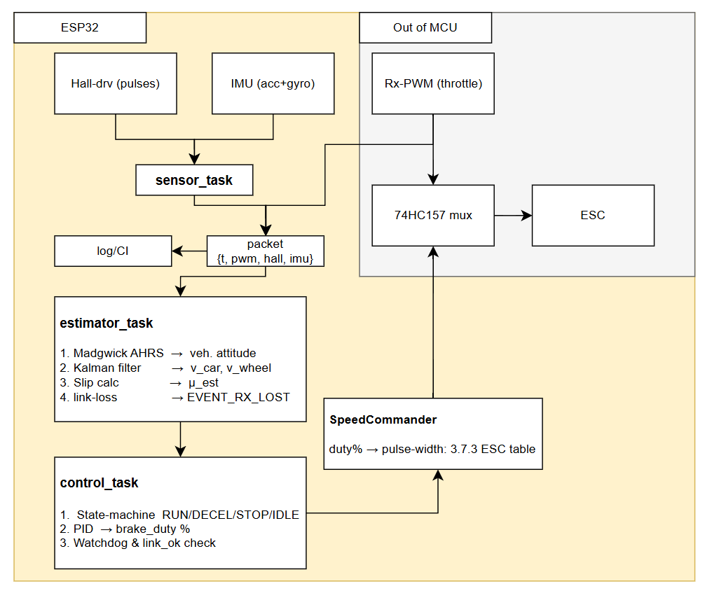
3.7.2 Two nested control loops
| Loop | Period | Plant | Goal | Controller | Comment |
|---|---|---|---|---|---|
| Inner | 10 ms | rear wheel dynamics | μ (slip) → 0.15 | PID | |
| Outer | event-driven | vehicle state | safe states | 4-state machine | Guards against wind-up, link loss, zero-speed stall. |
State transitions:
RUN ─► DECEL  (link lost OR driver pulls trigger)
DECEL ─► STOP (v_car < 0.3 m s⁻¹)
STOP ─► IDLE (brake_duty == 0 for 500 ms)
IDLE ─► RUN  (driver reapplies throttle)
3.7.3 ESC as an electronic brake
No caliper, no servo; the ESC does it all.
| Pulse | Meaning (QuicRun "F/B" mode) |
|---|---|
| 1.70 ms | 100 % forward throttle |
| 1.50 ms | Neutral / coast |
| 1.30 ms | 100 % dynamic brake |
| < 1.30 ms | Reverse (disabled by clamping) |
Firmware constants:
#define ESC_NEUTRAL_US 1500
#define ESC_BRAKE_MAX_US 1300   // never go lower
SpeedCommander linearly interpolates between those limits; the pwm_mux_driver toggles its GPIO at 2 kHz. If the MCU crashes, the RC filter on the mux select pin discharges in ≈ 25 ms and hardware flips back to the radio lane—meeting FR-1b even with dead firmware.
3.7.4 Calibration checklist
- Set QuicRun to Forward/Brake (hold button 3 s, 1 LED flash).
- Radio end-point calibration: full-throttle → full-brake → neutral.
- Record neutral pulse with logic analyser → update
ESC_NEUTRAL_US. - Road test: log
μ_est, adjustPID.kpuntil damped (ζ ≈ 0.7).
3.7.5 Verification hooks
| Hook | What it proves |
|---|---|
| Logic-analyser on mux output | Pulse drops to 1.30 ms ≤ 100 ms after Rx loss (FR-1b). |
| High-speed video + tape | 30 km h⁻¹ → 0 in ≤ 1.2 m (FR-2). |
| Replay harness | Deterministic stop distance on log playback. |
This richer ABS section now ties sensors, maths, hardware PWM and safety-mux into one coherent narrative—readers can replicate or audit every step.
3.8 The FPV Link: Seeing Through the Car's Eyes (and why it beats Wi-Fi in a race)
The WildFire Nano AIO module bundles sensor, NTSC encoder and 5.8 GHz VTx on one 4 g board. That saves you an extra ribbon cable and, more importantly, slices the latency pie:
| Segment | Typical Wi-Fi (ESP32 MJPEG) | WildFire analogue |
|---|---|---|
| Sensor → encode | 20 ms (JPEG) | 3 ms (direct CVBS) |
| PHY / air link | 50–80 ms (2.4 GHz) | 4–6 ms (5.8 GHz) |
| Decode → LCD | 15 ms (browser GPU) | 6–8 ms (goggle LCD) |
| Total | 75-120 ms | 13-17 ms |
Because the module is camera-internal, the ESP32 does nothing for the race-day video stream: zero CPU, zero DMA, zero risk. The ESP still provides a Wi-Fi MJPEG tap for pit-lane tuning; you simply choose which feed to watch.
Safety tie-in: fpv_monitor reads the WildFire RSSI pin through fpv_rssi_adc.c. If signal fades below -90 dBm for half a second the task raises EVENT_FPV_LOST, which the OSD blanks and the controller logs. The event can even trigger a gentle "pull over" profile if you like,just add a handler in FailsafeManager. Worst-case current draw at 200 mW is < 300 mA; a 470 µF low-ESR cap right at the VTx pins stops brown-outs when the power amplifier keys up.
So you get laboratory-friendly Wi-Fi plus race-worthy analogue,each with its own latency-budget test hook,without burdening the microcontroller or poking extra holes in the ABS loop.
4 End-to-End Traceability - Kitchen-Table Proof
| Req | Functional blk | Physical element(s) | Software module(s) | Verification hook |
|---|---|---|---|---|
| FR-1a | Estimation | ELRS Rx PWM line + timer counter | estimator_task (LinkLossTimer) | Logic-analyser: > 120 ms gap raises EVENT_RX_LOST |
| FR-1b | Control | 74HC157 mux (sel GPIO) + QuicRun ESC | control_task, mux_feed_task | Scope: pulse hits 1.30 ms ≤ 100 ms after FR-1a |
| FR-2 | Control / Sense | Hall sensor + BMI270 IMU | estimator_task, PID | Hi-speed video + pandas stop-distance script |
| FR-3 | Telemetry | OV2640 cam + ESP32 Wi-Fi | cam_task, stream_task | LED-flash latency rig |
| FR-4 | Telemetry | SD-card logger | csv_logger | pandas integrity check |
| FR-5 | Telemetry | WildFire Nano VTx | fpv_monitor, osd_task | IR-scope: analogue latency |
| CO-1 | BOM | All parts | tools/bom.xlsx | CI budget line |
5 Risks & Mitigations Snapshot
| Risk | Like. | Impact | Mitigation |
|---|---|---|---|
| Mux select line stuck HIGH (firmware bug) | Low | High | Power-on reset pulse; self-test toggles at 2 kHz |
| Wi-Fi congestion inflates MJPEG latency | Med | High | Auto channel scan + analogue fallback |
| Buck-converter noise corrupts IMU Z-gyro | Low | Med | Π-filter on 3 V3 rail + IMU ground-flood |
| Hall encoder misses pulses > 30 km h⁻¹ | Med | Med | Oversample + de-bounce; add second magnet if track demands |
| VTx over-temp in enclosed shell | Med | Med | Therm-pad to chassis; auto power-back-off at 65 °C |
© 2025 Victor Retamal - Project Notes.