Practice Project for Systems Engineering - Part 1
Imagine you're at your local RC club race. Your RC buggy rockets down the straight and snap, the radio link dies.
No brakes, no hope. Or you're threading hair-pins, but the video feed lags so badly you might as well be driving blindfolded.
That nightmare is the frustration this project sets out to erase.
"I want my WLtoys buggy to brake by itself if the radio dies,and I want live video that isn't a slideshow—all for pocket money."
This post captures the front-end thinking, mission framing, requirements, trade studies, and a first-cut architecture, before a single line of firmware is written.
DISCLAIMER: I haven't done extensive testing for the hardware pieces included in the project. Since this is an exercise, I "trusted" GPT o3 with the estimates for the latencies and such. If I were planning to carry on with this project, a whole verification and validation process would need to be done for those parts.
PS: I already got the platform :)
1 Where This Is Headed
Why this section exists We open with a crystal-clear finish line. Numbers first; the figures anchor every future argument.
TARGET PERFORMANCE
- Braking 30 km h⁻¹ → 0 in ≤ 1.2 m
- 30 fps FPV with ≤ 120 ms glass-to-glass latency
Primary feed = analogue 5.8 GHz (6-8 ms); secondary = MJPEG Wi-Fi (bench) - Slam-stop on radio loss in < 100 ms
These numbers are the compass. They are deliberately "edge-case hard" so that normal operation feels effortless.
Whenever we debate a design choice, we drag it back to this bullet list and ask: does it move the needle or just add weight?
2 From Idea to Mission Definition
Before solder smoke and Git commits, systems engineering forces us to tame the foggy idea.
We interrogate the concept with three questions: who hurts, how do they hurt, what single outcome removes the pain?
| SE Step | Key Question | Draft Answer |
|---|---|---|
| Stakeholder analysis | Who benefits? | Club racers, track marshals, future devs. |
| Need extraction | What hurts? | Long braking, risk of runaway, laggy or dropped FPV. |
| Mission wording | Outcome? | "Stop safely and stream low-latency video with hobby parts." |
The table may look trivial, but it took three sticky-note sessions to collapse sprawling wish-lists into defined mission points with a single declarative sentence.
-
Mission M.1 — Braking Safety
Bring the buggy from 30 km h⁻¹ to a full stop in ≤ 1.2 m, or within 100 ms of radio loss, without wheel lock-up. -
Mission M.2 — Low-Latency Situational Awareness
Provide a forward-facing FPV stream with ≤ 120 ms glass-to-glass latency, using hobby-grade parts and keeping the extra electronics under $ 60.
Those two missions become the filters for every requirement that follows.
2½ The V-Model - Why Every Box Has a Mirror Test
Most hobby builds stumble because tests are bolted on last.
The V-model forces us to architect and pre-plan proof in one sweep: decompose on the left, verify on the right.
Stakeholder Needs  →  System Req  →  High-Level Design  →  Detailed Design  →  Code
↑                                                                              ↓
│                           Integration & Verification                         │
└──────────────────  Subsystem / Component Tests  ←  Unit Tests  ←  Build  ←───┘
Left side → we slide downwards, refining fuzzy pains (long braking, laggy FPV) into the SMART "shall" statements you'll meet in Section 3, then into the architecture snapshot of Section 5.
Right side → we climb upwards, using the Verification Matrix (Section 7) to prove—unit by unit, then subsystem by subsystem—that the real buggy matches those early promises.
| V-Step | This-post Artefact |
|---|---|
| Stakeholder Needs | Section 2 table |
| System Requirements | SMART table (Sec. 3) |
| High-Level Design | Functional/physical map (Sec. 5) |
| Detailed Design / Code | Part 2 |
| Unit & Component Tests | Logic-analyser script, latency rig |
| System Verification | Brake-distance hallway test |
| Validation (real value?) | Hopefully someday a cool video |
Reading down the left-hand leg you feel abstraction thinning; reading up the right, you see confidence thickening.
That symmetry is the mental model you'll spot in every later decision.
3 SMART Requirements - Yardsticks We'll Build To
How this table was born We ran a ruthless word-workout: every "should" became a "shall", every vague adjective gained a number, every number gained a kitchen-table test.
| ID | "Shall" Statement (measurable) | Planned Verification |
|---|---|---|
| FR-1a | Detect Rx PWM loss > 120 ms | Logic-analyser script. |
| FR-1b | Drive the ESC to a ≥ 100 % brake pulse within ≤ 100 ms of FR-1a firing. | Logic-analyser + scope. |
| FR-2 | Rear-wheel ABS reduces 30 km h⁻¹ stop distance to ≤ 1.2 m. | Tape-measure & high-speed cam. |
| FR-3 | Analogue FPV latency ≤ 20 ms (95 %-ile). | IR-LED scope rig. |
| FR-4 | MJPEG Wi-Fi stream ≥ 30 fps, latency ≤ 120 ms. | LED-flash latency rig. |
| FR-5 | Log IMU, wheel speed, PWM at 100 Hz to SD-card. | CSV inspection. |
| CO-1 | Prototype electronics ≤ $60. | Excel BOM. |
Note the twin latency requirements: FR-3 guards the race-day analogue link, FR-4 covers the bench-friendly Wi-Fi feed.
Cost (CO-1) sits beside functional goals, because clever design that busts the budget still fails the mission.
4 Trade-Space Exploration - Survival of the Smartest
Mental model: widen the funnel first, then hack it down with constraints from Sec. 3 until one option per row survives.
| Topic | Options Considered | Decision | Key Rationale |
|---|---|---|---|
| Control link | Wi-Fi, BLE, 2.4 GHz FHSS | ELRS 2.4 GHz Rx/Tx + HW PWM-mux | Lower packet loss, hardware failsafe reverts to radio if MCU dies |
| FPV transport | Analogue 5.8 GHz, MJPEG Wi-Fi, H-264 Wi-Fi, digital HD | Hybrid: WildFire Nano + ESP32 MJPEG | Analogue nails latency/range; Wi-Fi is bench-easy. |
| ABS sensing | 4-wheel quadrature, 1-wheel Hall, IMU-only | 1 Hall + IMU | Adequate accuracy, low weight & cost. |
| Compute board | Custom PCB, STM32, ESP32-S3-CAM dev-kit | ESP32-S3-CAM | Built-in cam & Wi-Fi, $10, community tooling. |
The exercise isn't about "best tech", it's about best fit against the SMART grid.
Notice how latency and cost killed several shinier options.
5 Architecture Snapshot
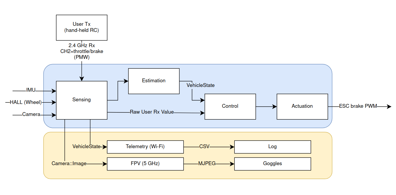
Reading the diagram:
- User Tx → 2.4 GHz Rx The hand-held transmitter delivers throttle/brake PWM. The 74HC157 mux defaults to this lane if the ESP32 watchdog stops toggling. If that link goes silent for more than 120 ms, FR-1a's failsafe slams the brakes.
- Sensing ingests both vehicle data (wheel Hall count, IMU) and the human command from the Rx, time-stamping everything at 100 Hz.
- Estimation fuses sensor cues, computes slip, and forwards a clean state vector to Control.
- Control blends the user's throttle intent with ABS logic and watchdogs; the output is a shaped PWM duty that Actuation feeds to the ESC via the mux's second lane.
- In parallel, Telemetry pushes logs over Wi-Fi, and the dedicated FPV chain beams low-latency analogue video to the driver's goggles.
Picture each arrow as a contract: data-rate, latency, and verification hook are already pencilled in. Anything that can't find a home here loops back to Trade-Space for a rethink.
6 Sub-System Focus - FPV & Telemetry
Ideally, the latency budgets will require extensive exploration and expertise, followed by thouroug verification. However, since this is a starting point exercise, I'm going to trust the search of gpt o3 for this values. If I were to implement this at some point, a huge chunk of time will go into verifying all the LLM claims.
Analogue (primary)
| Hop | Target ms | Comment |
|---|---|---|
| Cam exposure → RF mod | 3 | CMOS NTSC sensor. |
| Air link | 4 – 6 | 25 mW, clear LOS. |
| RF demod → LCD | 6 – 8 | Typical goggles. |
| Total | < 20 | Meets FR-3 comfortably |
Wi-Fi (secondary)
| Hop | Target ms | Comment |
|---|---|---|
| Sensor → JPEG | 20 | ESP32 HW encoder. |
| JPEG → Wi-Fi | 5 | Memory-to-PHY DMA. |
| Air link | 50 – 80 | 2.4 GHz crowd-dependent. |
| Decode → LCD | 15 | Browser GPU. |
| Total | 75-120 | Meets FR-4 given RF hygiene. |
Take-away: the system tolerates Wi-Fi jitter because the race-critical feed is analogue.
7 Verification Matrix
Reading tip: scan a row, mentally imagine the bench rig that proves it, feel the risk evaporate.
| Req | Tool | Pass Criterion |
|---|---|---|
| FR-1a | Logic-analyser | ≤ 120 ms gap |
| FR-1b | Logic-analyser | ≤ 100 ms to 1.30 ms pulse |
| FR-2 | High-speed video | ≤ 1.2 m |
| FR-3 | IR scope rig | ≤ 20 ms (95 %) |
| FR-4 | LED latency rig | ≤ 120 ms |
| FR-5 | pandas log check | No missing samples |
| CO-1 | Excel BOM | ≤ $60 |
Spend ten minutes sketching each rig now; save ten days of "why is it slow?" later.
Ready for the Right-Hand Side?
Everything above cements the why and the what of this project. But diagrams don't stop runaway cars—firmware, task graphs, and PCB traces do. In Part 2 we pivot from "paper promises" to "design you can compile"
If Part 1 gave you the mental scaffolding, Part 2 will hand you the wrench set. Grab a coffee and jump in → Practice Project for Systems Engineering - Part 2.
© 2025 Victor Retamal - Project Notes.